LED Clock
Overview
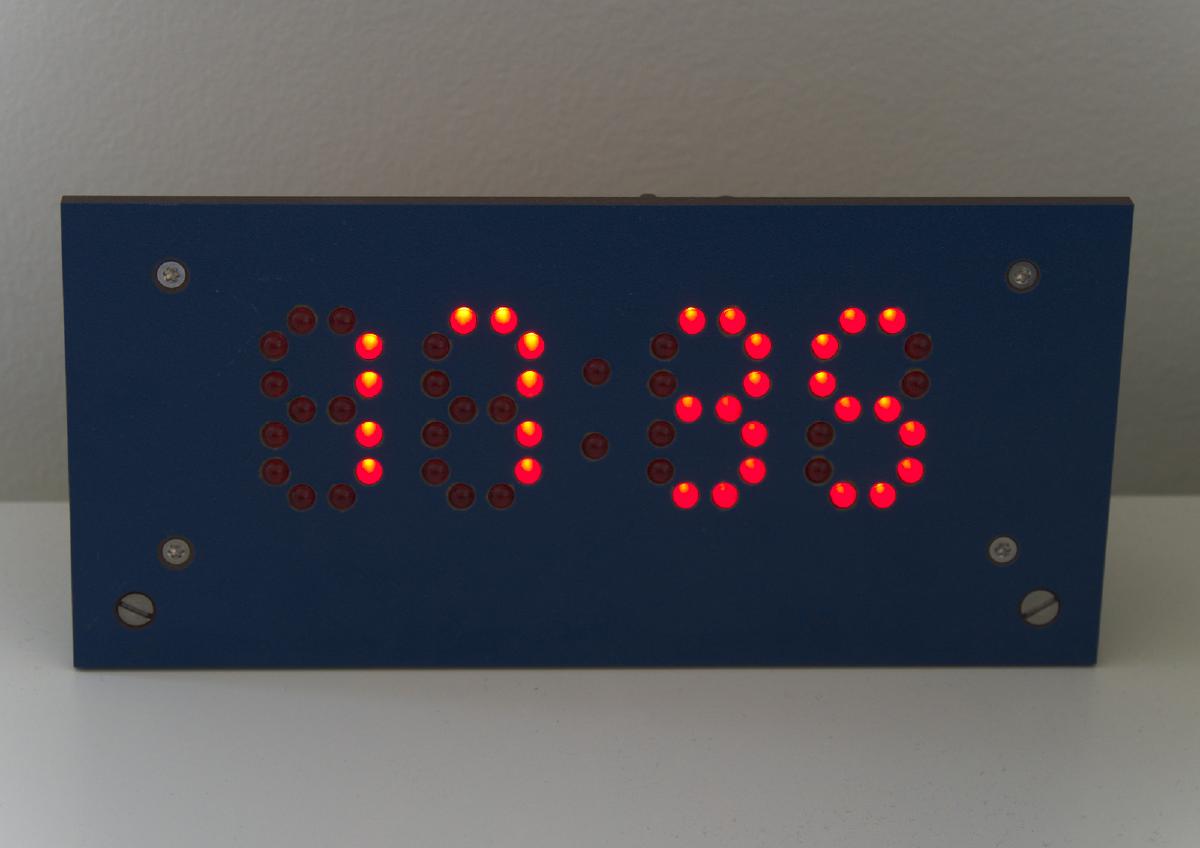
During my apprenticeship I once had to make a counter with a seven segment display made of individual 5 mm LEDs. This display inspired me to make a digital clock with four of those digits.
The clock has two buttons to adjust the time forwards or backwards. The LEDs are automatically dimmed in dark environments thanks to an LDR measuring the ambient brightness.
Images
Details
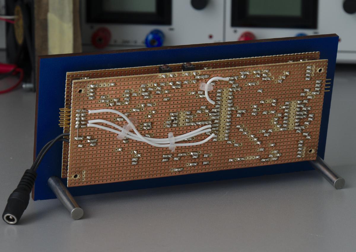
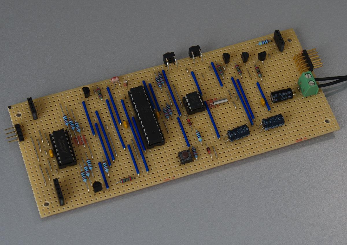
The circuit is built on two stripboards. The front board contains all the LEDs of the display. It is connected to the rear board with pin headers are on the front board.
The clock is controlled by an ATmega328p microcontroller. At first I had used the Arduino bootloader to program it over the UART. After I had learned how to program AVR microcontrollers without the Arduino framework, I also added a connector for an AVR-ISP.
To keep time I used a DS1307 real time clock. Because I didn’t have a holder for a button cell battery, I instead used two capacitors as a power backup. This way, the clock is able to keep running through short power outages. The time can be adjusted with two buttons on the top. The longer a button is pressed, the faster the time changes.
In order to control all the segments of the display with the limited I/O pins of the microcontroller, I used two tricks. Thanks to a BCD to 7 segment decoder, each digit only needs four pins. The four digits are then multiplexed so that the 28 segments can be controlled using only eight pins.


